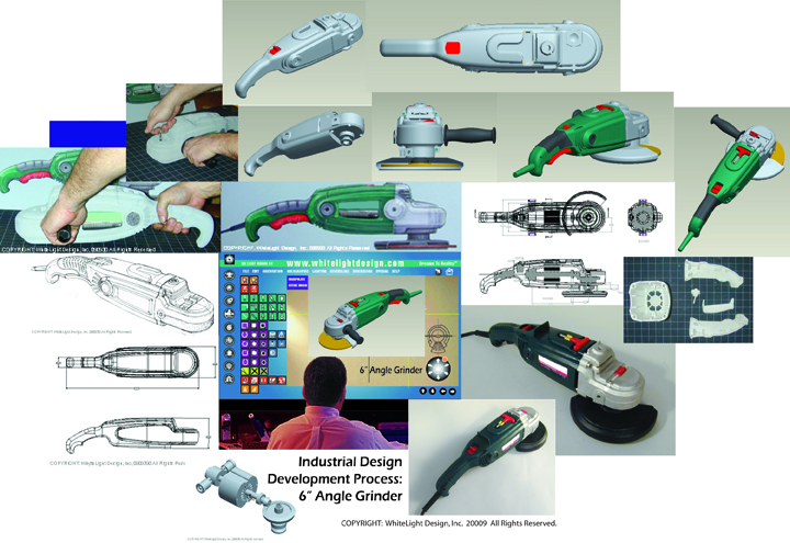
CAD 3D Development Process
Practical application of 3D CAD data can be utilized to construct complex electronic and mechanical mechanisms (simple machines that make larger more complex machines operate), perform 3D part mechanical assembly and mechanism modeling, tolerance and fit checks, Finite Element Analysis (FEA) and Rapid Prototyping (RP – CNC, SLA, SLS), and Computer-Aided Machining or Manufacturing (CAM), for machine – mold, die, tool or part creation, defining tool paths and cutting rate speeds, for creating tooling cavities and cores, manufacturing robotics assembly control, part inspection, etc. The process of CAD – CAE – CAM development allows the entire invention–product development process to be managed from concept to production assembly line robotics, including resource allocations, manpower management and fulfillment, minimizing costs, cycle time, and reworks.
3D CAD Development
The process of product development using CAD through prototyping, predictive analysis, and manufacturing starts with the idea and thumbnail sketch combined with industrial design and extensive industry experience to deliver a well-built 3D CAD model and data file with seamless translation of the CAD files (i.e. .stp or .igs) throughout the entire process. This process takes significant investment, planning, and experience to deliver a profitable product design solution. With the integration of Computer Numerical Controlled (CNC) and Computer Aided Machining (CAM) and Rapid Prototyping and the Industrial Designers, Engineers Prototypers, Toolers, and ultimately the Machine Operators knowledge of natural and man-made materials, craftworking, forming, molding, and machining techniques, these tools create machine dedicated, automatic part builds or machine tool cutting command files. The Machine Operators must understand the product–part–assembly design intent as well as the properties, limitations, chemical and structural forces that are generated, released during and after the material removal or prototype build, and the resulting geometries, be it clay, wood, plastic, or metal.
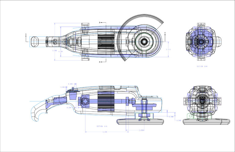
CAD 2D Drawings
The deliverables typically include request for quotation (RFQ) 2D drawings. The drawings may include orthographic and or isometric views the full assembly and individual part sheet drawings. The RFQ drawing package may include the Bill of Materials with quantity materials, manufacturing processes, color and finish specifications.


